The impulse response of the RC circuit example is ht 1 RC e tRC The response of this system to an input xt is then. Step Voltage Input RC Low pass filter circuit.
Pin On Electronics Tutorials
How does an RC circuit respond to a voltage step.

. The discharge voltage for the capacitor is given by. Thus an RC integrator circuit is one in which the output voltage V OUT is proportional to the integral of the input voltage and with this in mind lets see what happens when we apply a single positive pulse in the form of a step voltage to the RC integrator circuit. Handout on RC Circuits.
When something changes in a circuit as a switch closes the voltage and current also change and adjust to the new conditions. Find the equivalent circuit. RC circuits can be used to filter a signal by blocking.
Across the equivalent capacitor. Av β RcRb. Digital Electronic Fall 2003 RC RESPONSE Example Capacitor uncharged.
Recalling the form of the RC circuits step response we can anticipate how the circuit will respond to a square wave input of varying frequencies. The required filter bandwidth for linear response would increase to 393 MHz step size 5 V vs. Where V is the applied source voltage to the circuit for t 0 and R C τ is the time constant.
Capacitor charging for series RC circuit to a step input with time axis normalized by τ. Written by Willy McAllister. In that case if.
RC Phase Shift Oscillator Circuit Diagram. In the case of this circuit and the break frequency is in the neighborhood of 1 radsec. These are single time constant circuits.
Assuming exponential settling of the step input the required RC time constant τ is. The resistances R1 R2 and RE used to form the voltage biasing and stabilization circuit. For the natural response and for the step response where τ is the time constant.
Transient Response of an RC Circuit. The common emitter amplifier circuit elements and their functions are discussed below. Procedures to get natural response of RL RC circuits.
Inductor kickback 2 of 2 RC natural response - intuition. Biasing Circuit Voltage Divider. Find the initial conditions.
Neureuther Version Date 090803 EECS 42 Intro. A resistorcapacitor circuit RC circuit or RC filter or RC network is an electric circuit composed of resistors and capacitorsIt may be driven by a voltage or current source and these will produce different responses. This assumes the mux switches.
III Cbetween the detectors in. Apply voltage step of 5 V We know this because of the pre-transient dc solution V0 and post-transient dc solution V5V. Circuit Elements and their Functions.
In the circuit below the switch is initially open so before time t 0 there is no voltage feeding the circuit. Human-friendly formats let you enter and display values concisely. The transient response curve of RC circuit increases and is shown in Figure 3.
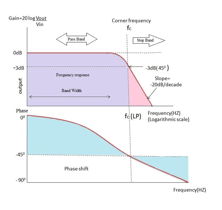
A low-pass filter is the complement of a high. RC step response solve 2 of 3 RC step response example 3 of 3 RC step response. Step Response of RC Circuit.
Exactly the RC networks phase angle can be expressed as. Find the time constant of the circuit by the values of the equivalent R L C. 15 cm apart and list-mode data was acquired by step-ping a 1 mmdiameter22Na point sourcesame as used in Sec.
2 c shows the response of low-pass RC circuit to a step input and the expression is valid only when the capacitor is initially fully discharged. Mixed-mode circuit simulation lets you simulate analog and digital components side-by-side. Preferably an easy RC network can be expected to include an op which directs the input with 90 o.
A low-pass filter is a filter that passes signals with a frequency lower than a selected cutoff frequency and attenuates signals with frequencies higher than the cutoff frequency. RC natural response - intuition. SPICE-like component models give you accurate results for nonlinear circuit effects.
This is known as a step input. The biasing circuit needs to establish a proper operating Q-point otherwise a. If the capacitor was initially charged to a voltage V o less than V then the exponential charging equation would be.
We solve for the total response as the sum of the forced and natural response. Single Pulse RC Integrator. The exact frequency response of the filter depends on the filter designThe filter is sometimes called a high-cut filter or treble-cut filter in audio applications.
V c t V 0 e. But in actuality the phase variation will be below this because the capacitor employed within the circuit cannot be perfect. The RC step response is a fundamental behavior of all digital circuits.
This article focuses on the circuit requirements and trade-offs in designing the front end. The response of the RC circuit is called a transient response or step response for a step. When a single step voltage pulse is applied to the input of an RC.
We will verify our intuition with a hardware-based experiment in the next section. Once the switch closes the supply voltage V s is applied indefinitely. Directly write down the.
V o V1 e-1RC Figure 2. 1115 V with a single channel. Through the equivalent inductor or initial voltage.
A first order RC circuit is composed of one resistor and one capacitor and is the simplest type of RC circuit. Clearly V out starts out at 0V at t 0 and approaches 5V. Natural response occurs when a capacitor or an inductor is connected via a switching event to a circuit that contains only an equivalent resistance ie no independent sources.
If the change is an abrupt step the response is called the step response.

Rc Circuit Formula Derivation Using Calculus Rc Circuit Circuit High School Math

Parabola Equations And Graphs Directrix And Focus And How To Find Roots Of Quadratic Equations Quadratics Quadratic Equation Solving Quadratic Equations

How To Transmit Audio With A Laser Pen Electronic Circuit Projects Circuit Projects Electronics Projects

Save Fuel With Hydrogen Hho Generators And Engine Controllers Save Fuel Hydrogen Generator Generation

Rc Circuit Formula Derivation Using Calculus Time Constant Rc Circuit Circuit

Opamp Integrator Circuit Diagram Electronic Oscillators Electronics Circuit

Build Your Own Microcontroller Based Pid Control Line Follower Robot Lfr Second Part Ermicroblog Microcontrollers Computer Technology Control

Pin On Lcd

Inductor Capacitor Initial Conditions Step Response Of Rl Rc And Rlc Circuits Sinusoidal Steady State Response Ad E Book Circuit Electric Circuit

Diode Clipping Circuits And Diode Clipper Circuit Diode Electronics Circuit

Pin By Kritika Mishra On Exams Sheet Music Exam
Build Your Own Microcontroller Based Pid Control Line Follower Robot Lfr Second Part Ermicroblog Microcontrollers Computer Technology Control

Pin On Raspberry Pi

Mesh Analysis Example Using Phasor Circuit Analysis Analysis Circuit Math
1

Pin On Electronics

Resistors In Series And Parallel Formula Derivation Resistors Series Formula

Pin On Radio Control

Rbse Solutions For Class 12 Physics Chapter 10 Alternating Current Rbsesolutions Rbsesolutionsforclass12physicschapter1 Physics Alternating Current Solutions